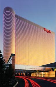
borgata hotel
atlantic city, nj
WELCOME to Christopher Shipper's Senior AE Thesis e-Portfolio!
BUILDING STATISTICS Building Name: The Borgata Hotel Casino & Spa Location: Atlantic City, NJ Building Occupant: Borgata Hotels Occupancy Function: Hotel Resort serving adjoining casino and spa Size: 2.2M Square Feet Stories Above Grade: 43 Project Team: Owner – Marina District Development Company Construction Date: N/A Cost: Estimated $1B (cost of hotel, casino and spa) Project Delivery Method: N/A ARCHITECTURE Architectural Design: This building is a high rise hotel that serves the adjoining casino and spa in Atlantic City. The building has a long floor plan with two large circular ends. This floor plan rises the height of the building. A large Borgata sign, the circular ends and the glazing with fluorescent lights serve as the signature for the building. The layout was of the floor plans were governed by cost efficiency. Since each of the hotel floors serve the same needs, the rooms and all their amenities, including electricity, plumbing and mechanical needs, were kept as consistent as possible. This allows for ease of construction and cost efficiency. Major Codes: 1996 BOCA and the 1997 New Jersey Uniform Construction Code Historical Requirements: No major historical requirments Major Zoning Restrictions: No major zoning restrictions, no height limitation Building Envelope: The vertical building envelope is made entirely of a glass curtain wall system. Curtain wall is composed of typical 3 ½”light guage mullions and insulated glass panels. The curtain wall is supported by structural tube steel girts. The roof slab is a 8 ½” structural slab. On the top the slab is a sepertation sheet topped with 3 inches of rigid insulation. On top of the insulation is a board layer topped with concrete. Structural System Mechanical System The hotel portion of the project is served by 2 Energy recovery systems (heat wheels). The guest room make-up air and exhaust are delivered through these systems reducing the cooling and heating load on the building. The pool on level 1 in the podium and on level 32 of the tower are each served with a dehumidification system utilizing chilled water as the cooling medium. Each air handler is provided with a Variable Frequency Drive. The remainder of the areas are all served with chilled water coil and hot water coil air handlers. The hotel tower is being provided chilled water and hot water from Marina energy. This is a utility company in Atlantic City that provides these services through a distribution network that has been designed to surround the entire Borgata site. The floor spaces all have individual control being served by a VAV bow with a hot water reheat coil. The VAV box will cut back to 50% prior to the reheat coil control valve opening to allow for heat. There are several exhaust systems within the new building; grease ductwork is used for the room service kitchen. Vapor exhaust for all the dishwashing areas. Miscellaneous exhaust systems are for toilet rooms, etc. The valet drive through is open to the outdoors and has been provided with an exhaust system to remove car fumes and an above ceiling heating system to prevent the floor above from feeling cold. Electrical System The hotel tower is powered by (12) 470 volt high voltage feeders from Marina Thermal (Quasi- Utility Co). These feeders supply three substations with (12) 470/480V transformers and distribution boards on levels B, 3 and 39. Each of these substations feed distribution panels (277/480V), transformers (480V/120/208V) and bus duct risers to hotel floors. Each hotel floor has several 120/208V panels for guest room lighting and power circuits. The podium floors ( B-3) have various panels and dimmers to feed lighting and power circuits. There are multiple power distribution panels (277/480V) for motor loads. There are panels, switches and emergency power feeders in the elevator control rooms for elevators. There are various panels and switches for pool motors and lighting.
|
|
| Home | |
| Christopher Shipper | |
| Building Statistics | |
| Thesis Abstract | |
| Technical Assignments | |
| Progress Log | |
| Thesis Research | |
| Thesis Proposal | |
| Presentation | |
| Final Report | |
| Reflection | |
User Note: While great efforts have been taken to provide accurate and complete information on the pages of CPEP, please be aware that the information contained herewith is considered a work‐in‐progress for this thesis project. Modifications and changes related to the original building designs and construction methodologies for this senior thesis project are solely the interpretation of Christopher Ankeny. Changes and discrepancies in no way imply that the original design contained errors or was flawed. Differing assumptions, code references, requirements, and methodologies have been incorporated into this thesis project; therefore, investigation results may vary from the original design. |
This is a student-generated Capstone Project e-Portfolio (CPEP) produced in conjunction with the AE Senior Thesis e-Studio.
This Page was last updated on September 5, 2007, By Christopher Shipper and is hosted by the AE Department ©2007